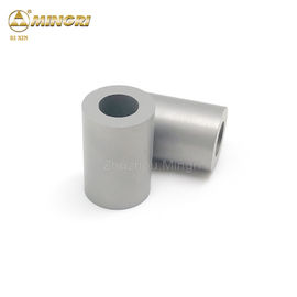
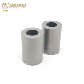
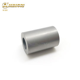
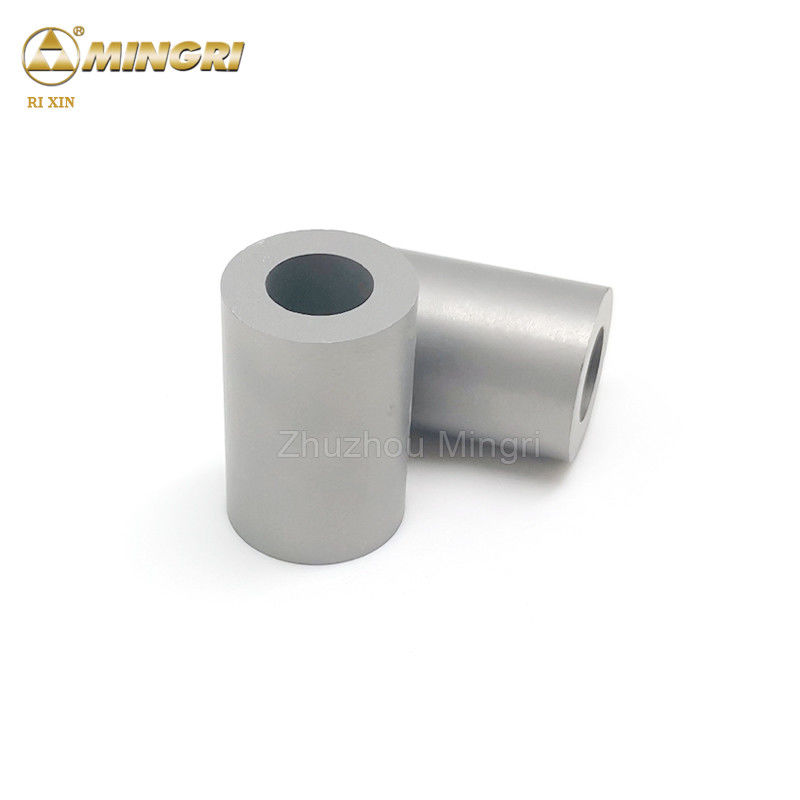
HIP Sintering Tungsten Carbide Die Cemented Carbide Stamping Dies Blanks Molds
Product Details:
| Place of Origin: | ZHUZHOU,HUNAN,CHINA |
| Brand Name: | RI XIN |
| Certification: | ISO9001:2008 ISO14001:2004 |
| Model Number: | rixin-1 |
Payment & Shipping Terms:
| Minimum Order Quantity: | 1 KG |
|---|---|
| Price: | Price varies according to the grade,weight and size |
| Packaging Details: | First in small cartons filled with cotton, then in bigger cartons. |
| Delivery Time: | 7-20 business days |
| Payment Terms: | D/A, L/C, D/P, T/T, Western Union |
| Supply Ability: | 50 Tons per month |
|
Detail Information |
|||
| Grades: | ML32,ML40,ML50,ML100 | Material: | TC+Cobalt |
|---|---|---|---|
| Application: | Stamping Die,Punching Die,Cold Heading Die,Cold Forging Die,Nut Forming Dies | Surface Treatment: | Blanks |
| Density: | 13.1 | HRA: | 83 |
| Strength: | 3200 | Key Word: | Cemented Carbide Punch |
| Highlight: | tungsten carbide tools,tungsten carbide tooling,HIP Sintering Tungsten Carbide Die |
||
Product Description
HIP sintering Cemented Carbide Stamping dies blanks wear resistance molds
Company introduction
Located in zhuzhou city,hunan province--the gungsten carbide base of China,zhuzhou mingri cemented carbide co. ltd .was established in May,2001 with the investment of 10 million dollars area of 33300 ㎡.With up-to-date production line ,advanced equipments,professional technicians and experts with national awards as the full time consultants,we have obtained 35 patents in invention,utility model and design,We have also passed ISO9001:2015 Certification in quality and ISO9001:14001 Certification in environment ,In recent years ,our capacity,quality and service have beeen further greatly improved due to plant expansion,introducion of advanced technologies and equipments at home and abroad and applicaition of 6S management.
Our Advantages
1 continuous production of tungsten carbide die over 18 years
2 total production quantity of tungsten carbide die up to 800 tons
3 widely exported to Europe,America,Australia, Brazil, India, Russia etc
4 We, Mingri CARBIDE, promise you the 100% raw material.
5 We, Mingri CARBIDE, quotation your order with 24 hours
6 We, Mingri CARBIDE , accept your order as per your requirements
Grade
ML32,ML40,ML50,ML100
![]()
Why choose us?
1. Zhuzhou Mingri has the richest molds stock of all kinds of cold and hot punching dies.
2. With stable relationship with our customers.
3. The most advanced tooling warehouse.
4. The largest production capacity and fastest delivery .
5. The most reliable testing machines for all specifications.
6. The best and reliable after service.
Applications:
1, tungsten carbide die use puching and stamping machine parts
2, tungsten carbide die use for drawing steel tubes and rods
3, tungsten carbide die ues for impact-resistant forging die, hot forging die and finished rollers
4, also use for nut wear resistant or impact resistant dies
5, use for nut forming die and high impact-resistant die
6, use for punching dies
Specification
| OD(MM) | ID(MM) | LENGTH(MM) |
| 6-100 | 0-ANY SIZE | 10-300 |
How to Run a Stamping Die at Maximum Speed with Minimal Breakage
Support Equipment Must Match Speed
Before looking at the tool design for speed capability, you should first understand the speed capabilities of the press and supporting equipment that will run the die. The tool’s speed capability is irrelevant if the press feeder, raw material payout, vision inspection, sensors, take-up reel, and conveyors cannot keep up.
When determining the capability of some of this equipment, you need to convert a linear speed such as feet per minute (FPM) or inches per second (IPS) into strokes per minute. To calculate the maximum speed of the equipment in SPM, you must divide the linear speed by the progression.
Balancing Speed and Breakage
Two factors establish a stamping die’s speed capability. The first is simply how fast the part can physically be produced. The second is at what speed the tooling fails (breakage).
The strength of carrying features (carrier), how high the part must be lifted, and the mechanical limitations of the springs and side action cams (mandrels) physically limit how fast the part can be made. Although problems associated with these items can cause tool breakage, they do not originate from tool breakage.
Design to Counter Physical Limits. In one way or another, each of the physical speed-limiting factors is dictated by the configuration, or design, of the part. When possible, it can be very helpful for you to work closely with the product designer to identify product compromises that make the part more “speed-friendly.”
1. For example, a part may be currently designed with very few areas where it can be attached between progressions, making the carrier too weak to feed the parts at high speeds without collapsing. A minor design change that makes the carrier more robust than can increase speed capability.
2. Other design compromises can be made without compromising part quality. For example, if the product design can be altered to eliminate the need for or reduce the travel of side action cams, or reduce the distance that springs need to travel, valuable increases in speed can be achieved.
3. Reducing how high a part must be lifted within the progressive die can help attain higher speeds. The most common way of limiting lift is by using more forming stations. A high form can be redesigned with multiple stations using lower forms that require less lift
Preventing Tool Failure
Tool failure is also very challenging. The cost associated with tool breakage makes it a hot topic. Although applying commonsense practices of robust tooling design certainly is helpful, there is no substitute for experience when you are designing tooling to prevent breakage. Often, when you are stamping smaller, more intricate parts, addressing breakage is easier said than done.
Not Just Thicker Parts. Designing dies to run at high speeds is not as simple as making a die component (including carbide punch, hardened steel bushings ) thicker in a specific area. In fact, sometimes that approach backfires, because it results in more reciprocating mass, therefore actually increase the potential for breakage.
Careful analysis of the forming and blanking pressures and their effect on the tooling is critical. Using strengthening techniques, such as the strategic placement of radii and chamfers on the tooling, is more effective.
Know the Breaking Point. To effectively stamp at high speeds, you must understand tool breakage and the point of diminishing returns. This is very tricky to balance. Because experience is crucial to establishing design practices that prevent breakage, you must first understand and balance between the long-term benefits of running faster and the short-term benefits of running slower. Because tool breakage is costly—downtime, design hours, and detail manufacturing—it is natural to feel compelled to reduce the speed so tooling breakage won’t occur.
Conversely, if breakage is carefully analyzed and redesigned, the knowledge attained can be used to improve the speed capability of future tools.
It’s common to hear frustrated toolmakers say, “Do you want to run the tool at 1,000 SPM all day with no problems, or do you want to run it at 1,200 SPM and have it break down every two hours?” The short-term benefit of running parts at slower, proven speeds is that you will not incur unplanned downtime and tooling costs caused by breakage.
Of course, the disadvantage of running at slower speeds is that you will never learn the weak points in a tool and therefore never attain the knowledge needed to maximize the speed it can be run. If you never push the speed limit, how will you ever know what the highest attainable speed is?
Feel free to contact me if any needs:
Whatsapp/wechat/phone:008618593402651
Facebook:Xiao Aimee
zhuzhou mingri cemented carbide co. ltd
Email:mr009@mrcarbide.com


